
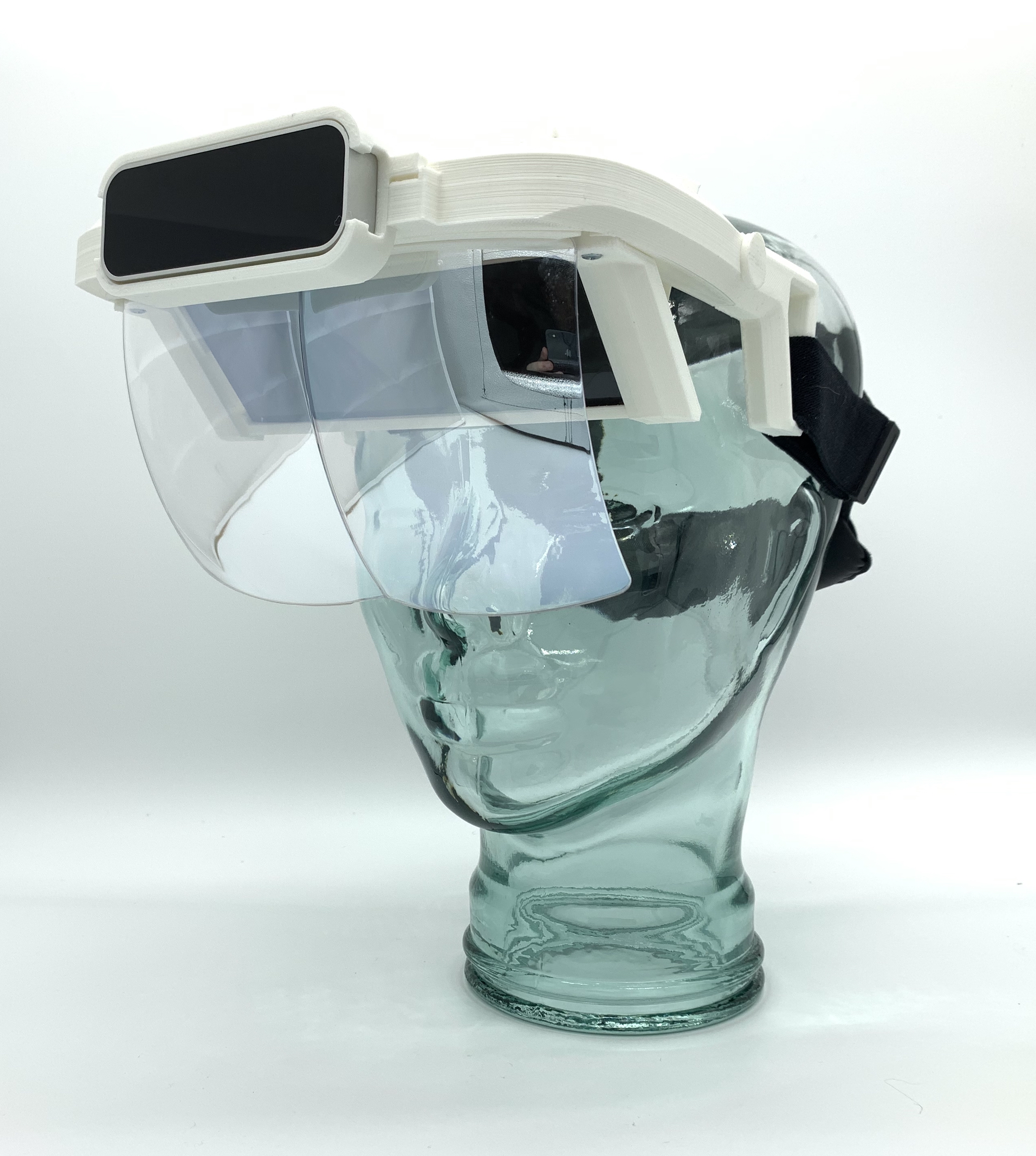
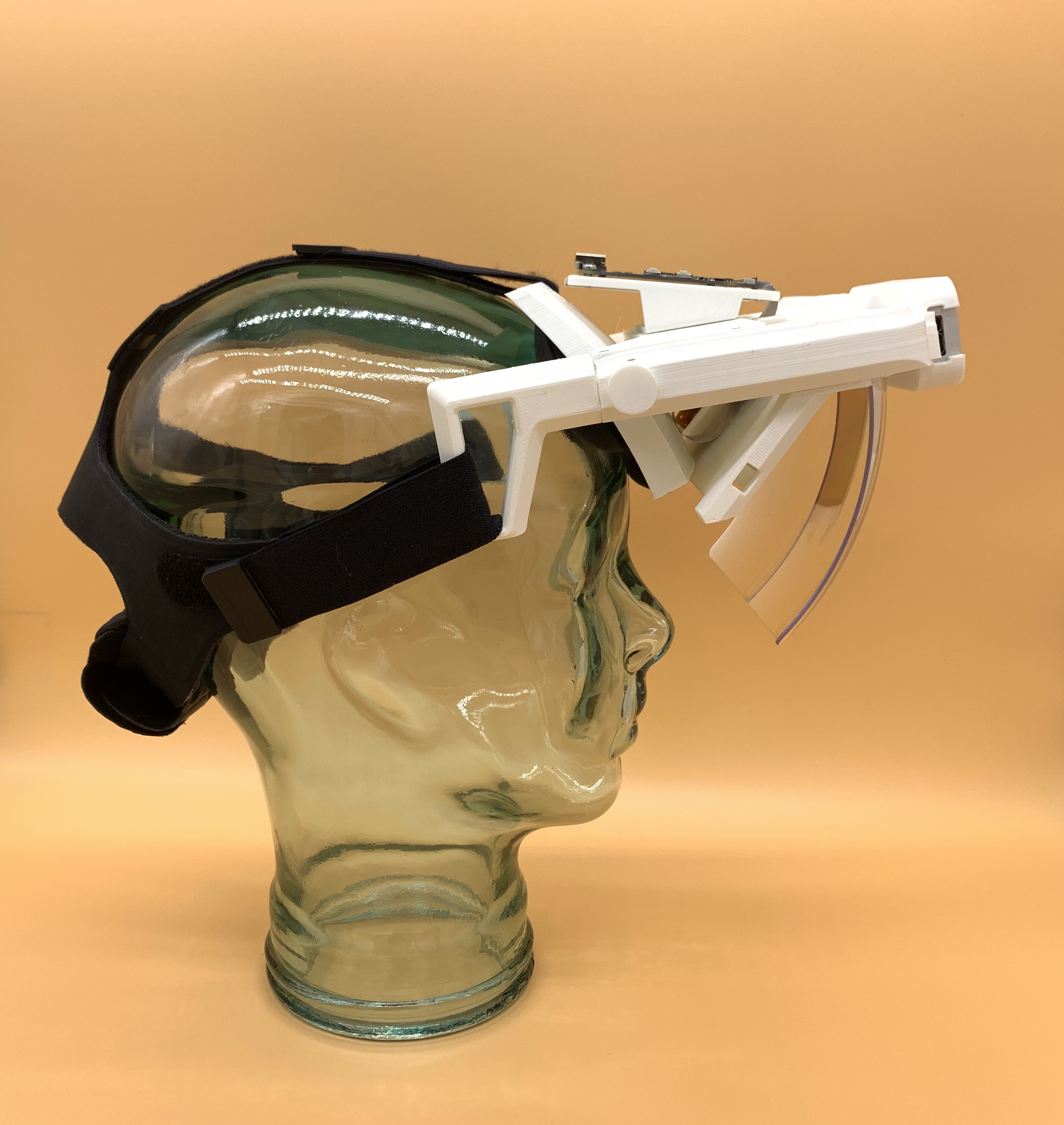
The Triton's design currently consists of 24 modular parts. 17 of which are custom designed 3d printed parts. There are 3 main parts which can be bought off the shelf: the display, vr head strap, and the optical reflector.
Below I've listed the official bill of materials (BOM). I've designated links to where you can purchase these parts, although there are a few alternatives as to where you can buy them. I've listed the estimated price of these parts but I have not factored in cost of shipping.
Assembling a Triton should take less than 30 minutes if you're familiar with having built a Project North Star. If this is your first time assembling an AR headset it may take closer to an hour. I've tried my best to provide clear and concise instructions to build a Triton Headset. This guide is still a work in progress and I appreciate constructive feedback to make it better.

Official BOM
Lasted updated 1/13/2021
| Ref. | Part name | Quantity | Link to Purchase | Est. Cost |
|---|---|---|---|---|
| A | 6 inch 2k LCD display | 1 | Aliexpress | $80.00 |
| B | AR Glass Reflectors | 1 | Aliexpress | $32.99 |
| C | HTC Vive standard strap | 1 | HTC Vive | $19.99 |
| D | Leap Motion | 1 | Amazon | $79.99 |
| E | 6mm Philips Screws | 100 | McMaster Carr | $4.66 |
| F | 3D Printed Parts | 17 | DIY or 3D Hubs | $7.15~$100.00 |
| G | Triton AR Launcher | 1 | Gumroad | $14.99 |
| H | Head padding kit | 1 | Knox Labs | $15.99 |
| I | PLA Plus Filament 1.75mm | 1 | Amazon | $26.99 |
| J | Hook and Loop Straps | 1 | Amazon | $10.99 |
Note: the shipping time when ordering from Aliexpress may take a while. Just be patient, I've ordered many times from them and have always received my package.
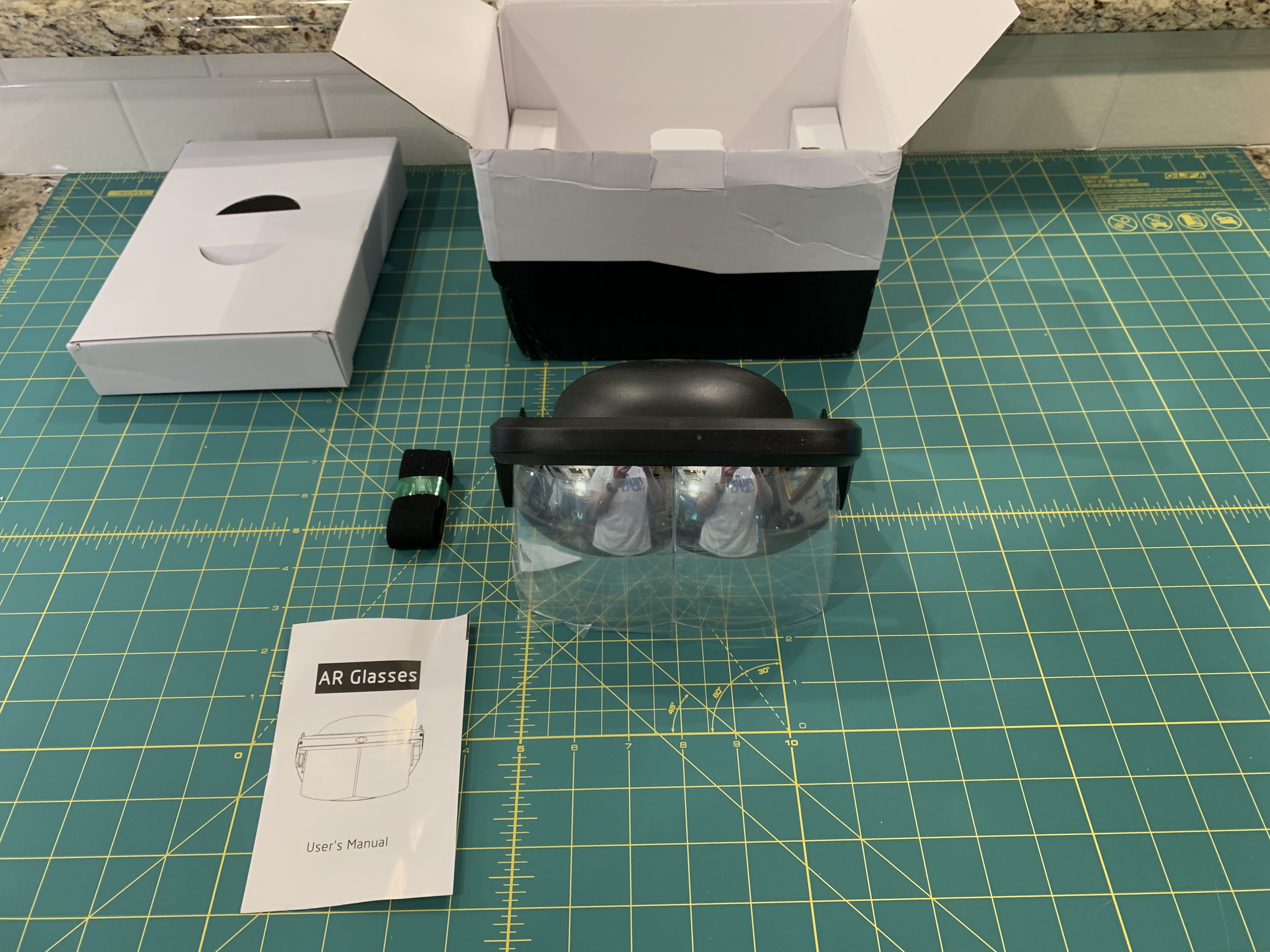
This LCD panel was developed by the WeiWei team. The resolution listed is 1440(RGB)x2560 with a refresh rate of 60Hz. What is shipped is shown below.

I recognize that 60Hz is considered to be on the low end for VR/AR HMDs. while there are other display options that offer 90Hz to 120Hz those are considerbaly more expensive. The 6 inch display works well for what I wanted on the Triton:
The reflectors are not custom designed by me. The reflectors come from an existing product called Intelligent Ar Glasses 3D. Anyone with expeirence in AR can easily see that these glasses are in the least bit intelligent. With the Triton Project we are going to turn this toy into an advanced AR system.
The optical architecture that these reflectors use are categorized as free-space combiners. They have a few properties that make them a good choice:
While this type of free space combiner is low cost they are still in order of difficulty to design and manufacture on your own. It is better to use an existing solution that is highly accessible and are available in large supply.

Turn the headset upside down and start to unscrew all screws that are visible. Make sure to use an appropriate screw driver as you don't want to strip the screws.

After the screws are removed you should be able to remove the bottom half from the top half. Once that is done you should have access to the optics bracket that is holding the reflectors. Remove the 2 screws on top.

Once those screws are removed the reflectors should be free to remove from the main bracket. The reflectors are still being held by another part I call the lens attacher. Just remove those 2 remaining screws.
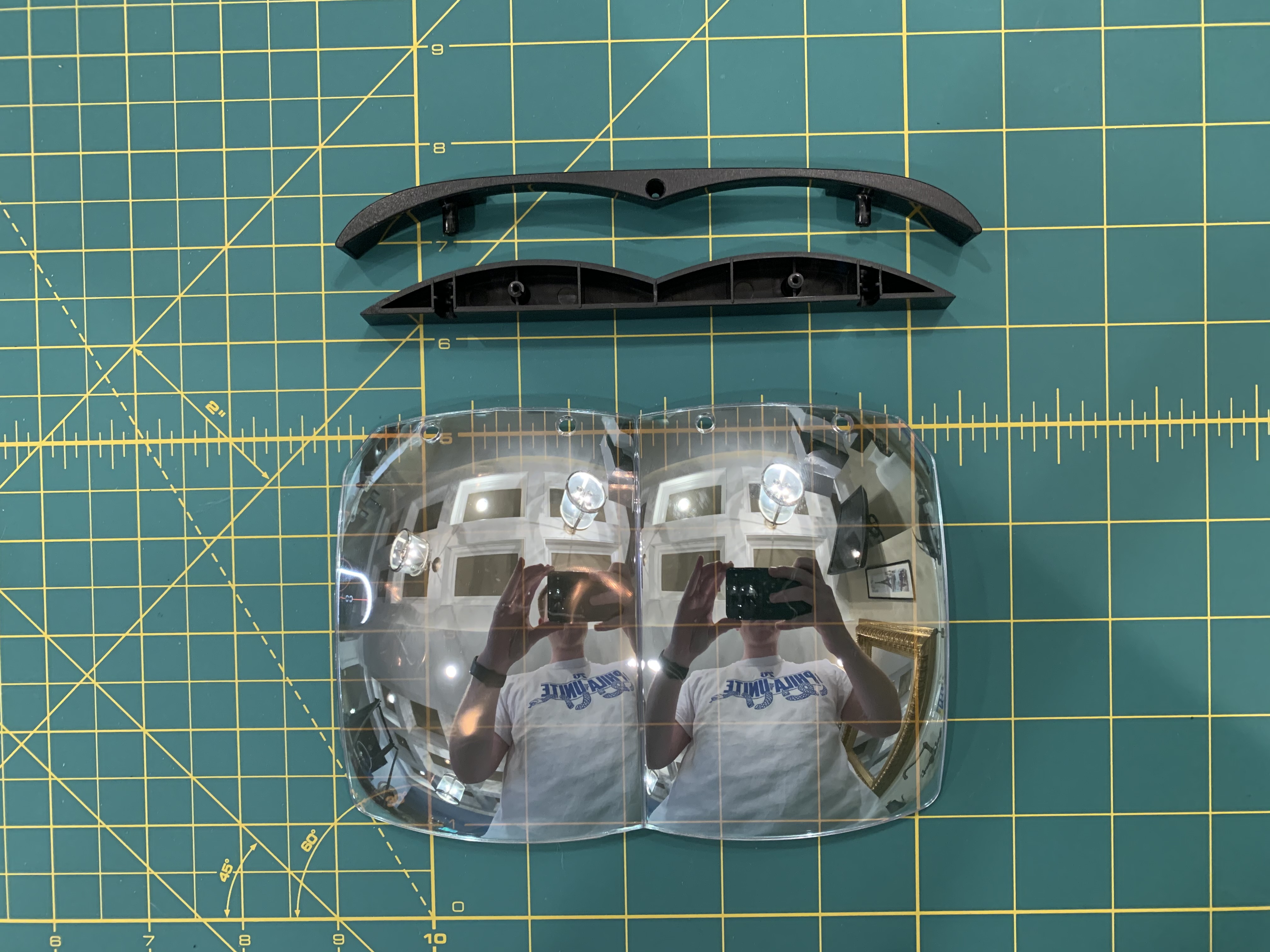
The reflectors should be completely free after that. Try to grip the reflectors from the side as you don't want to get finger prints all over its surface. Put the reflectors aside for now as they will be used later in the build tutorial.
I have given names to all of the 3d printed parts. You can reference the part names here
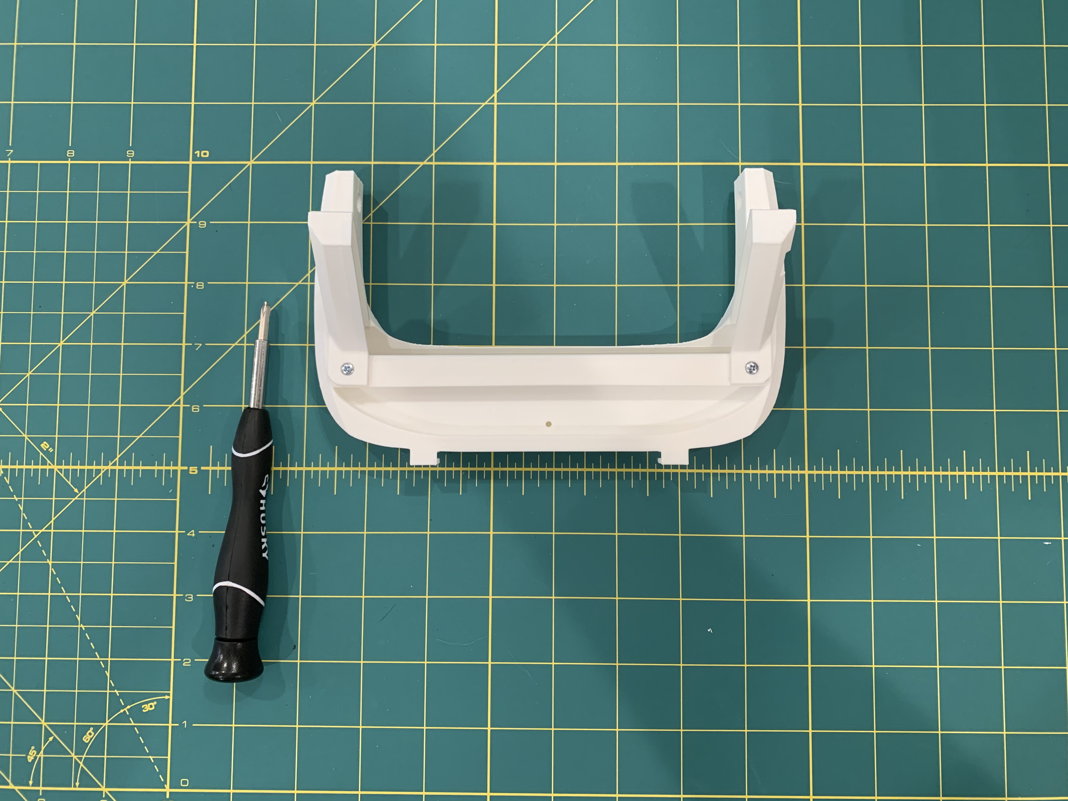
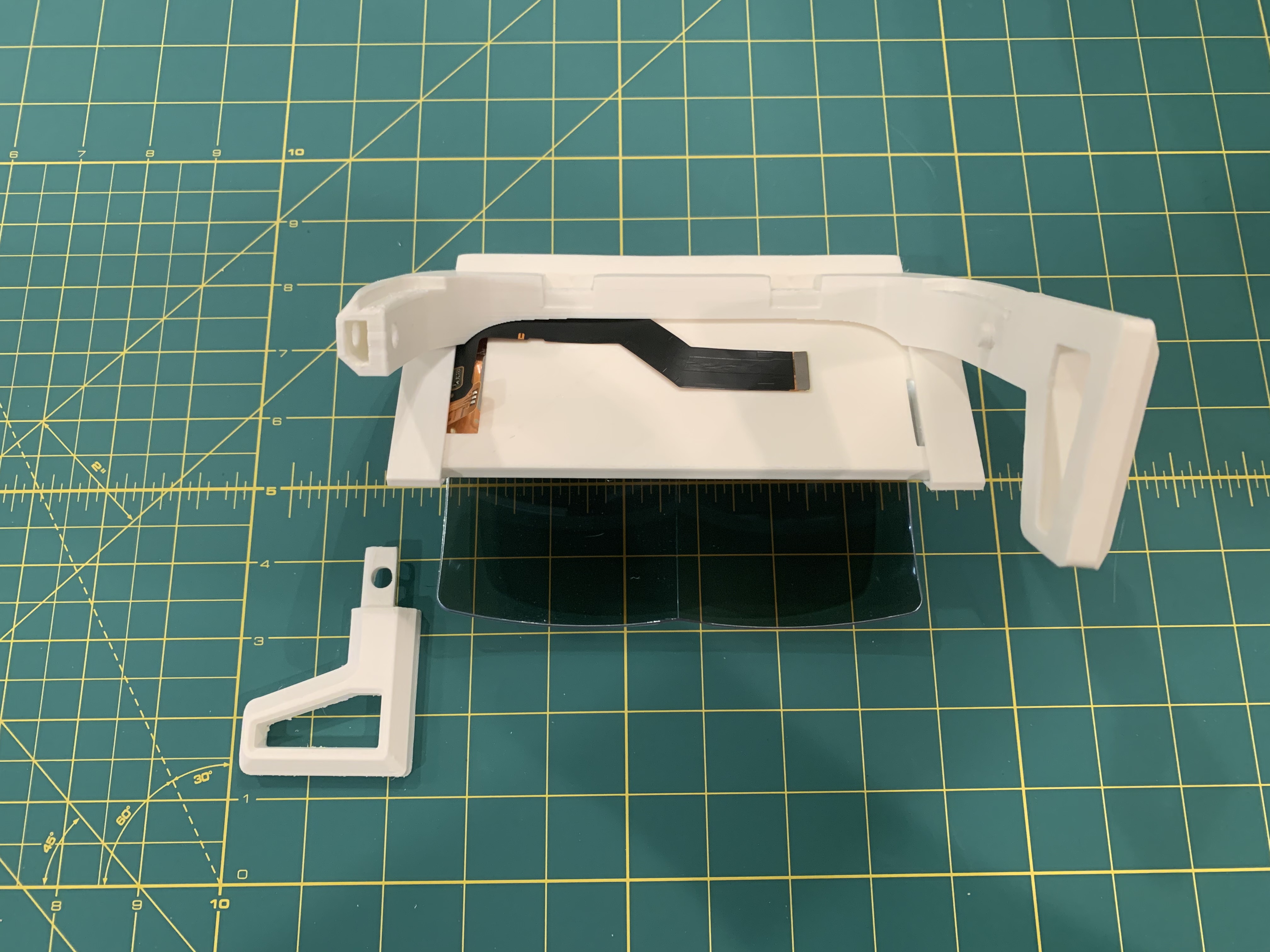
Take the left and right display brackets and insert them into the grooves. The use a screw driver to screw in the brackets until they are firmly secure.


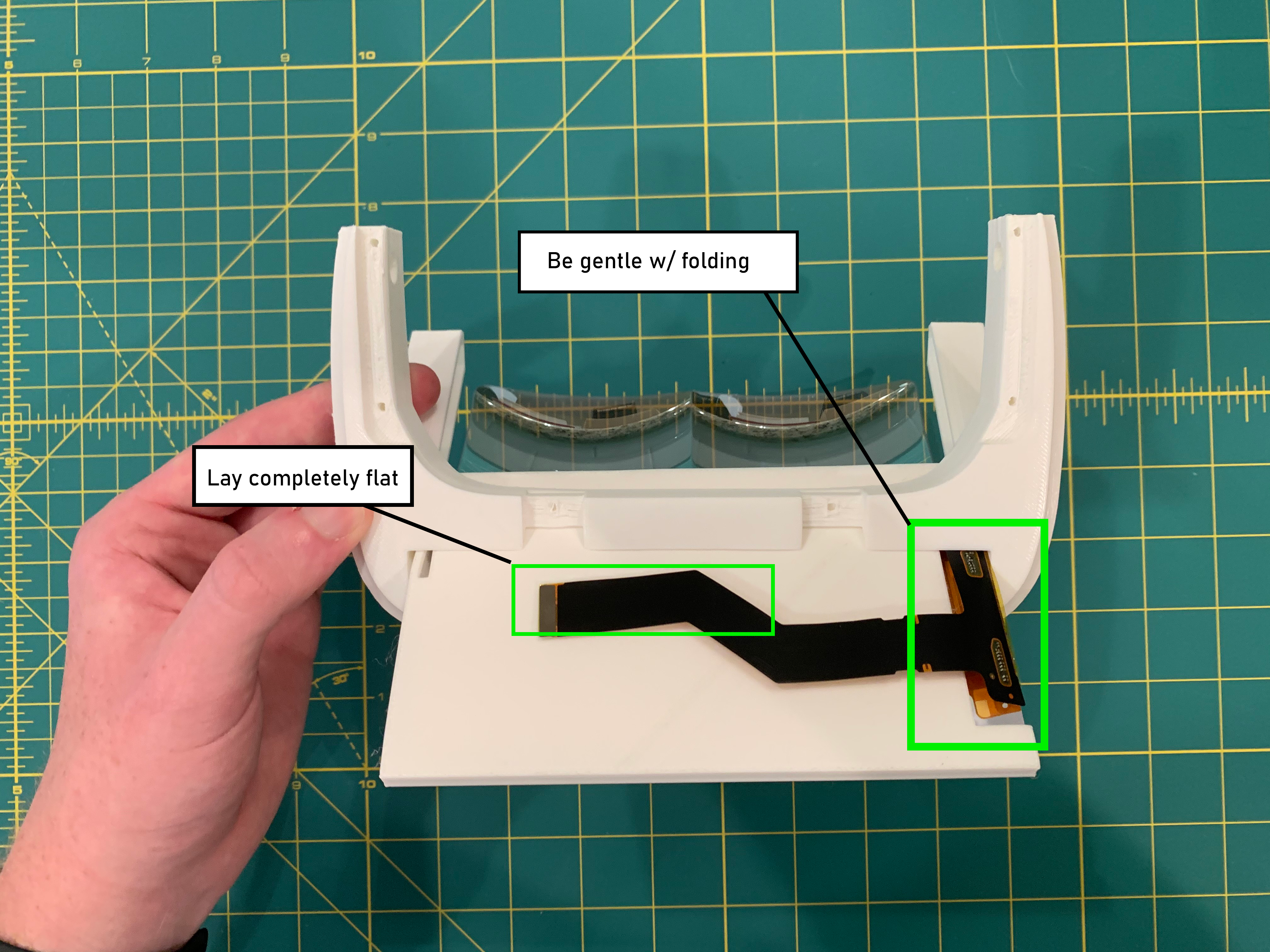
Slide the display panel into the display tray. While the screen is facing towards you the display tray should be inserted with the buckle clip on the side pointing to the left. Gently fold the FPC cable down towards the back surface of the display tray and slowly move the tray into the brackets.
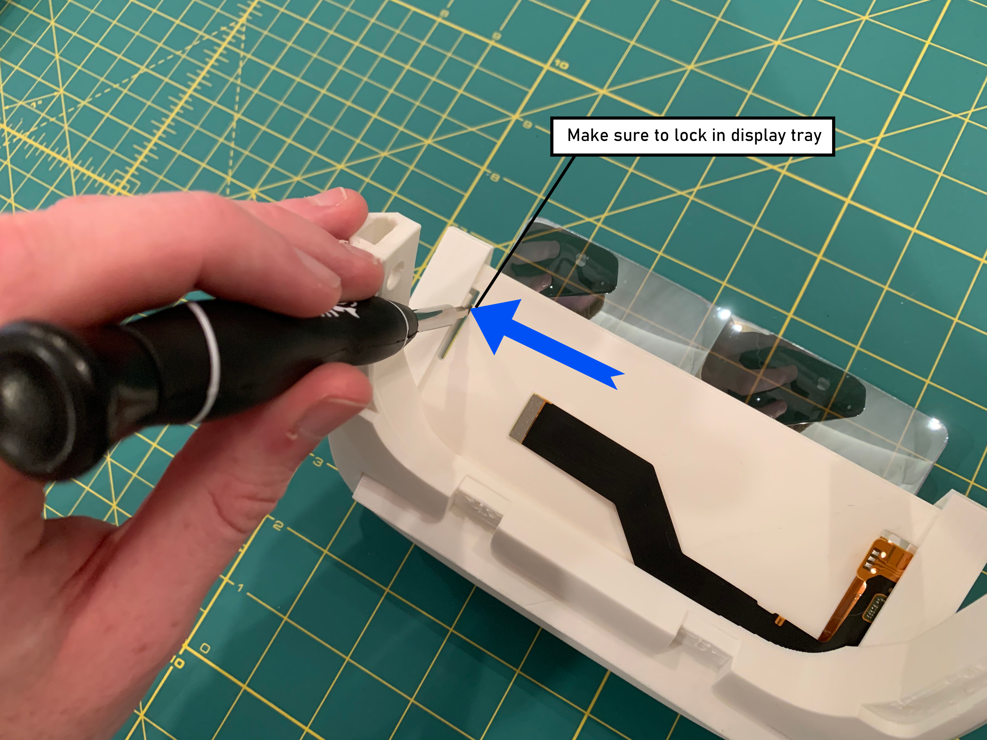

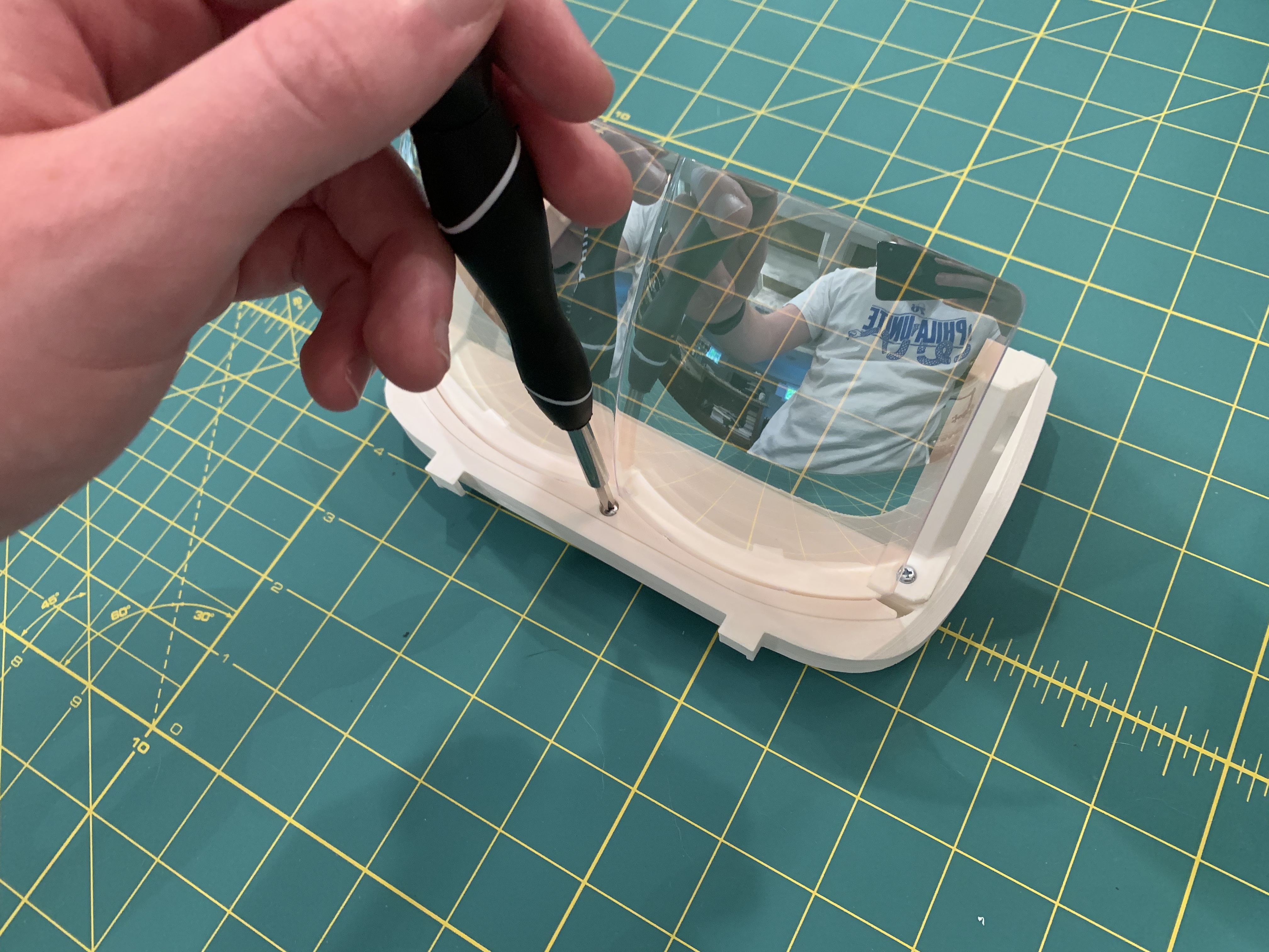
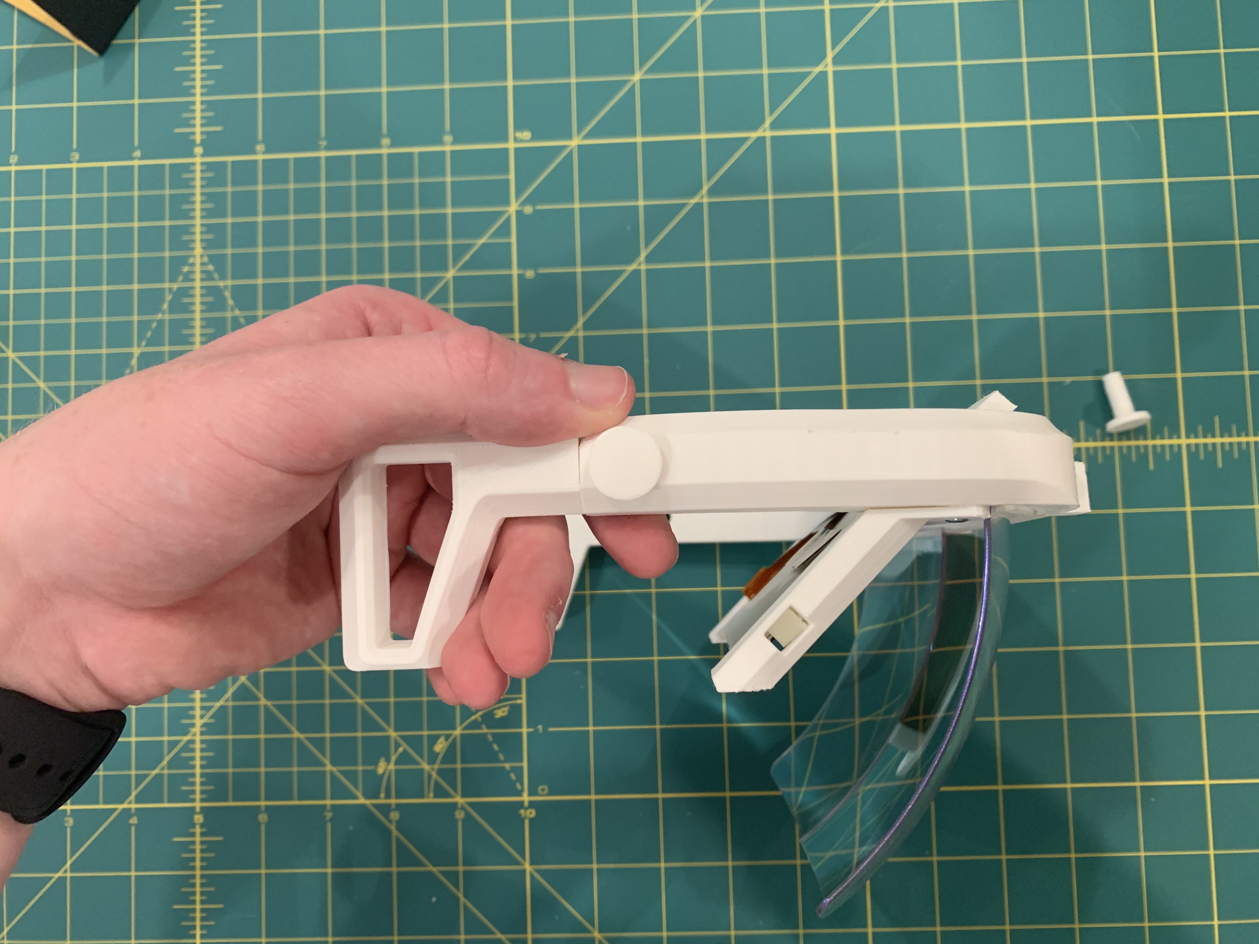
Slide the display tray all the way down until the buckle clips in to the bracket. You might want to double check that it clips in with a flat screw driver. This is what prevents the display tray from falling out. The display tray will protrude on top, I'm aware of this. If I had made the display brackets any longer than the display tray would have been visible in your line of sight affecting FOV. I decided to sacrifice the aesthetic and chose to preserve FOV. I am experimenting with smaller displays to fix this in a future hardware update.
If there is a lot of friction trying to insert the strap holders into the halo try sanding down the outer extension of the strap holder. If a strap holder doesn't go all the way in there may be some leftover filament from the support structures. Use an exacto knife to scrape out any remaining excess. After successfully inserting the strap holders insert the pegs through the holes of the halo. If there is a lot of friction try placing the halo on its side on a flat table and pressing down.

Use the 3d printed nuts to lock in the pegs. The end of the pegs should be threaded allowing for the nuts to easily twist on.


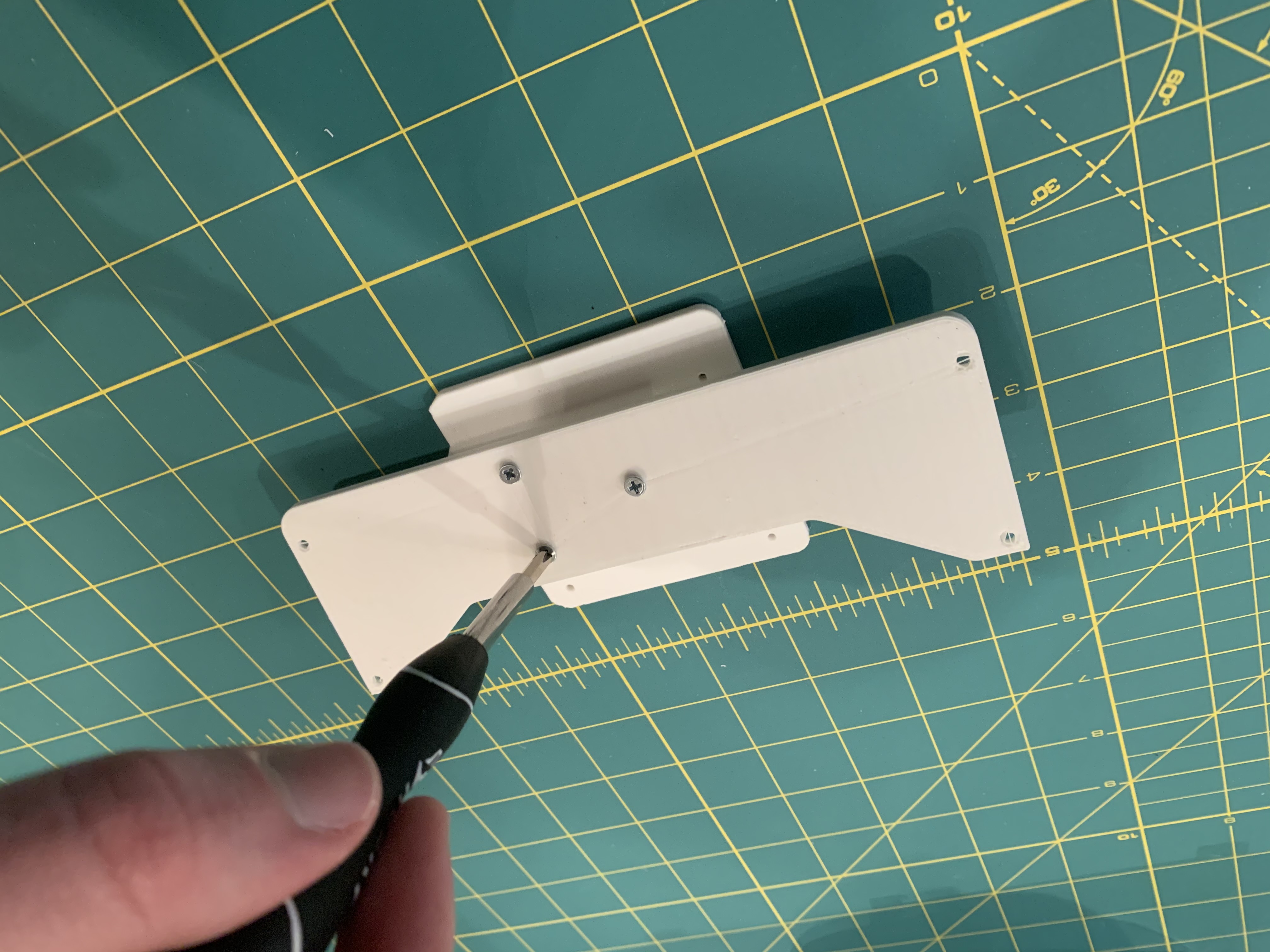
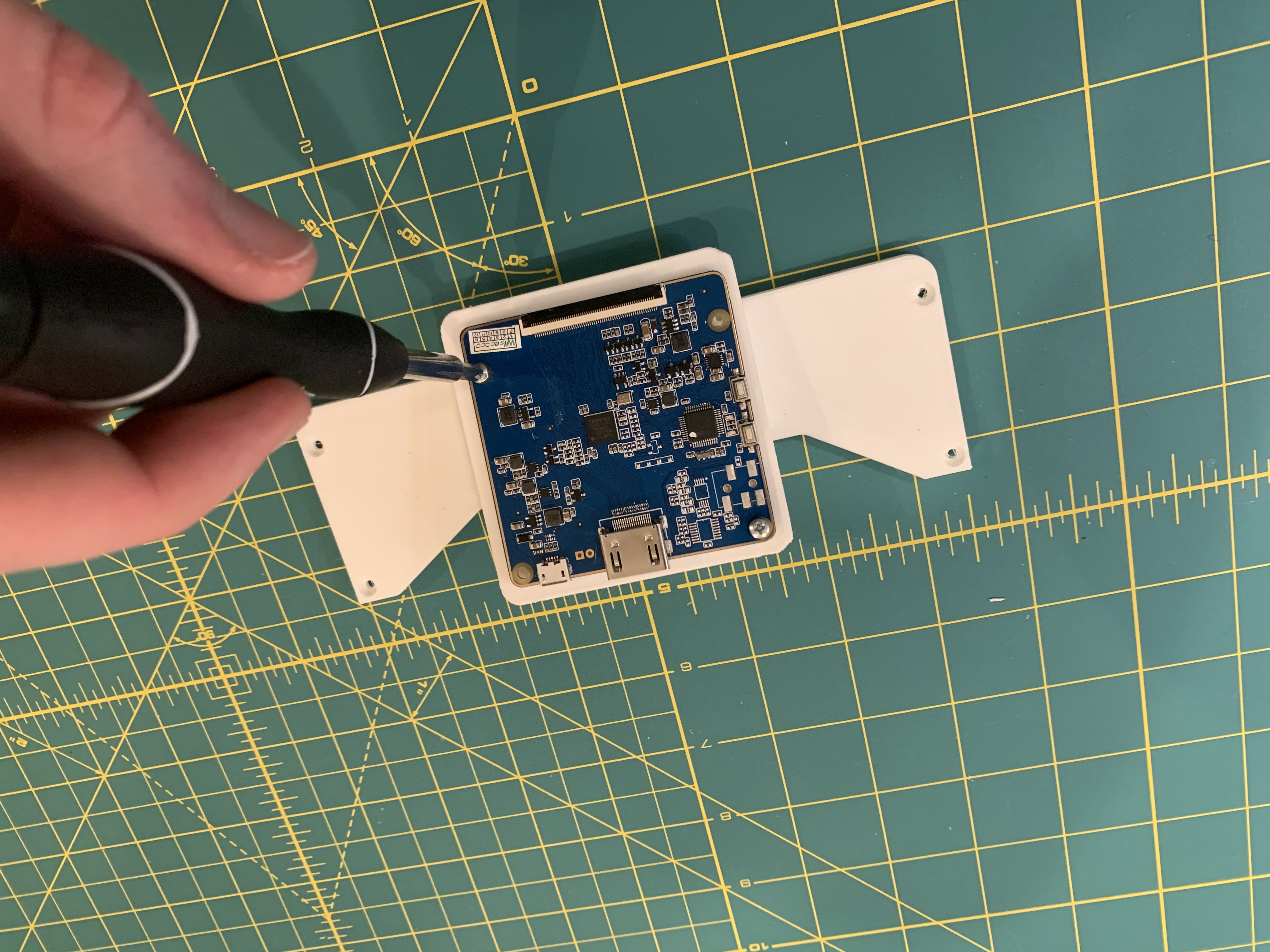
Line up the FM (FPC/MIPI) connector over the screws holes on the bottom of the rosen bridge. There are 4 screw holes but I recommend only using the 2 on the left side of the connector. The holes on that side of PCB are much larger and are less likely to damage the board. Tightly screwing those in will do more than enough to firmly secure the board.
After that is done I would recommend clipping in the MIPI flex connector. This will make your life easier as you will see how the rosen bridge gets attached to the halo.
Important Note: To firmly secure the rosen bridge to the halo I used a thicker screw {ADD SPEC} I would recommend first screwing into the holes of where the bridge is supposed to go inorder to create threads in the plastic. Firmly secure the rosen bridge to the halo. If the rosen bridge angles upwards from it being screwed so tightly its not a problem. The top cover will press it down creating enough for force to firmly secure the bridge.
Connect the fpc cable now as adding the head press in the next step will block access to the FM connector


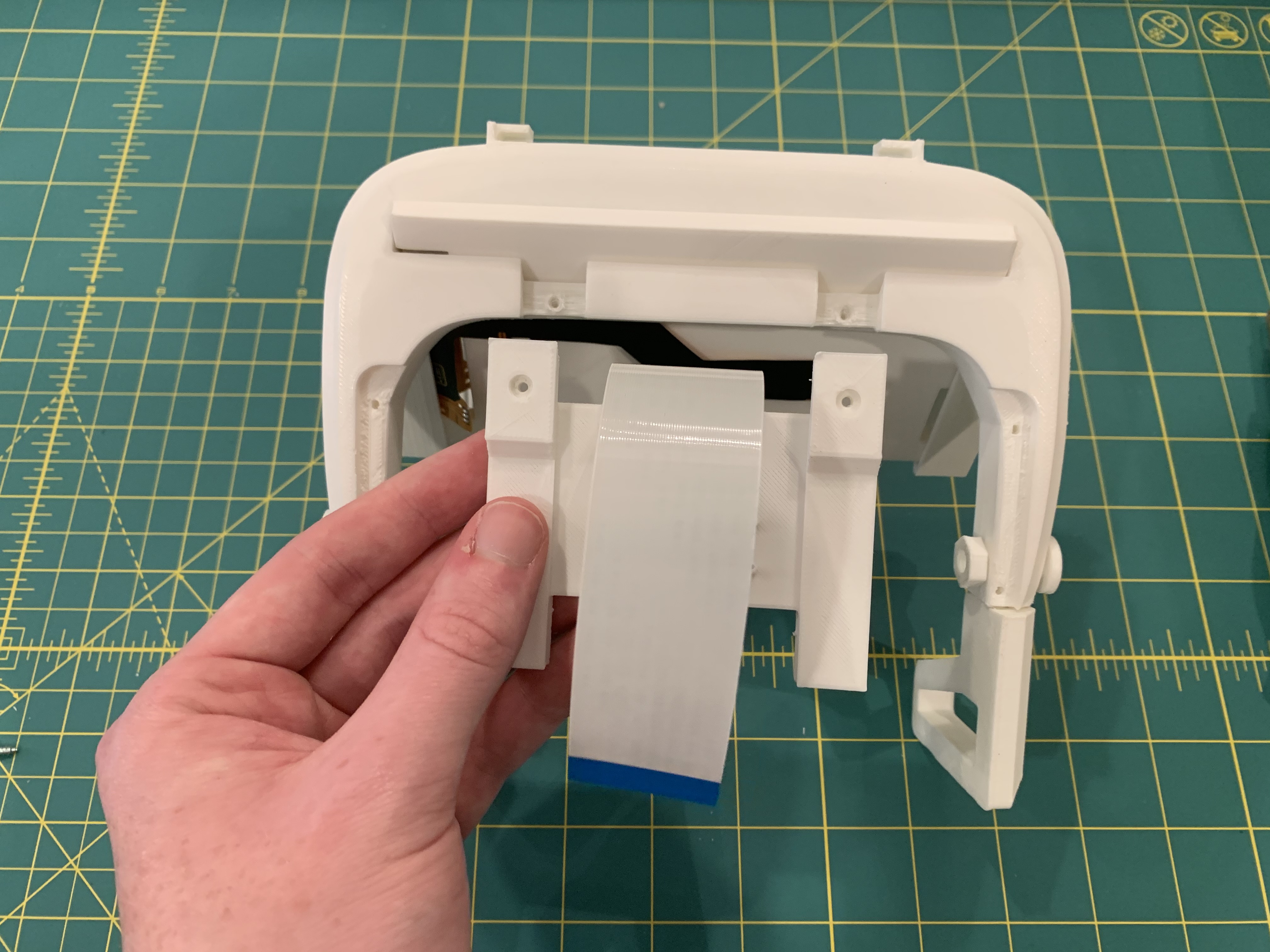
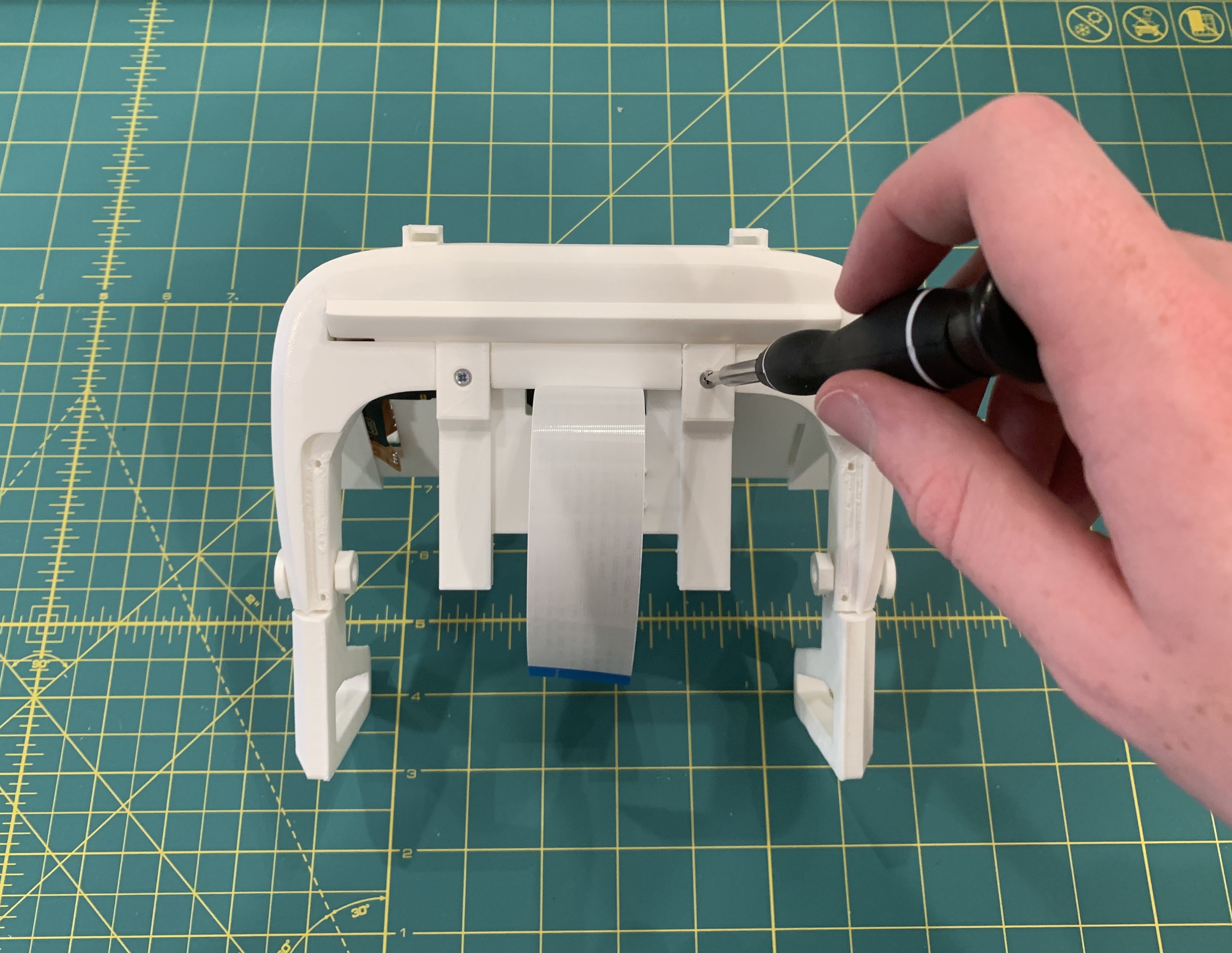
Line up the legs of the rosen bridge with the 2 cut outs on the head press. If you have trouble with legs inserting all the way than there may be access support material still inside the cut outs. Once successfully inserted use 2 screws from the back of the head press to securely fasten the head press to the rosen bridge.
This is only because the LCD driver mount will be slightly blocking the hole that the head strap pulls through.

Line up the LCD driver mount holes with the top cover and use 3 screws to securely fasten. Next you can use a minimum of 2 screws to fasten the LCD driver board to the surface of the driver stand.


Once the driver mount system is setup you can use 4 screws to attach the top cover to the top of the halo. You may need to slide down the flex cable in order to clip it into the board.

Lastly, you can then slide in the leap motion case. The easiest part of this assembly.

Congrats you've completed building the Triton. You can move on to part 2 to see how to prepare the headset for more user comfort.

The padding from the Ar glasses is quite comfortable on the forehead so we'll apply that to the Triton. The foam padding is velcroed onto the Ar glasses. You can easily with remove it by hand.
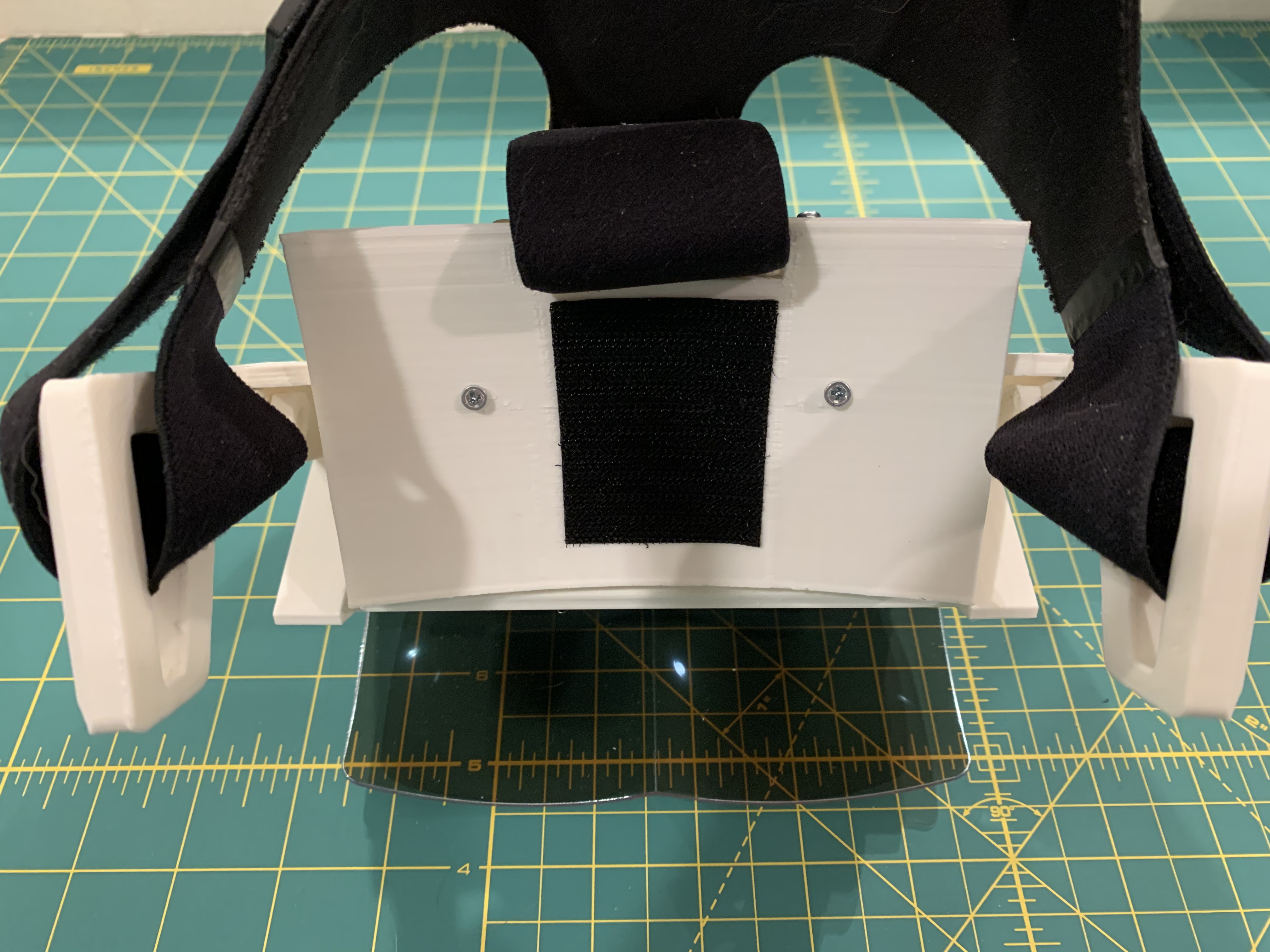
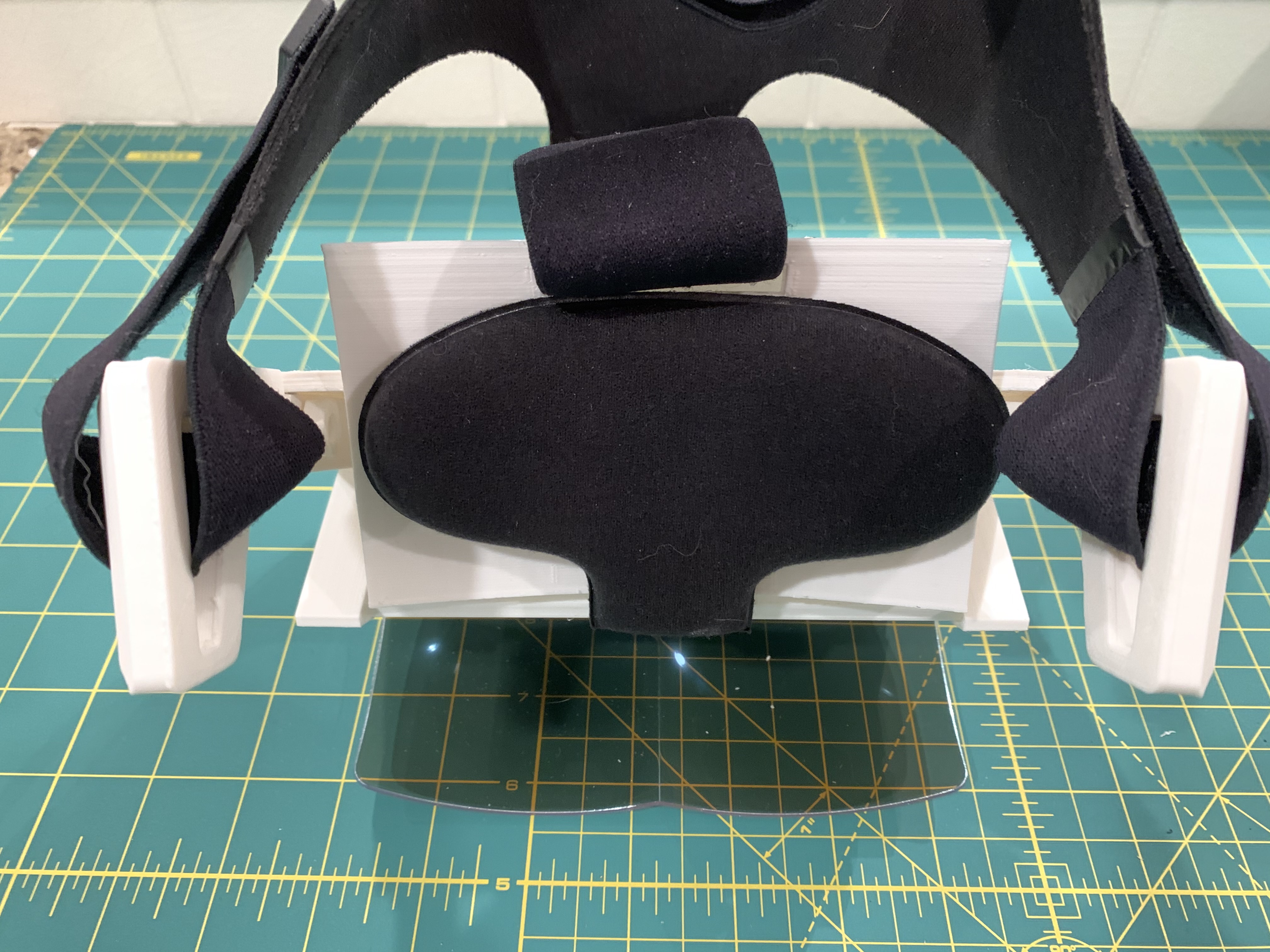
Next, cutout a rectangular piece of velcro and apply it to the center of the head press. Align and stick the padding onto the velcro. If you need to apply more velcro do so, but I have found 1 piece is sufficent.

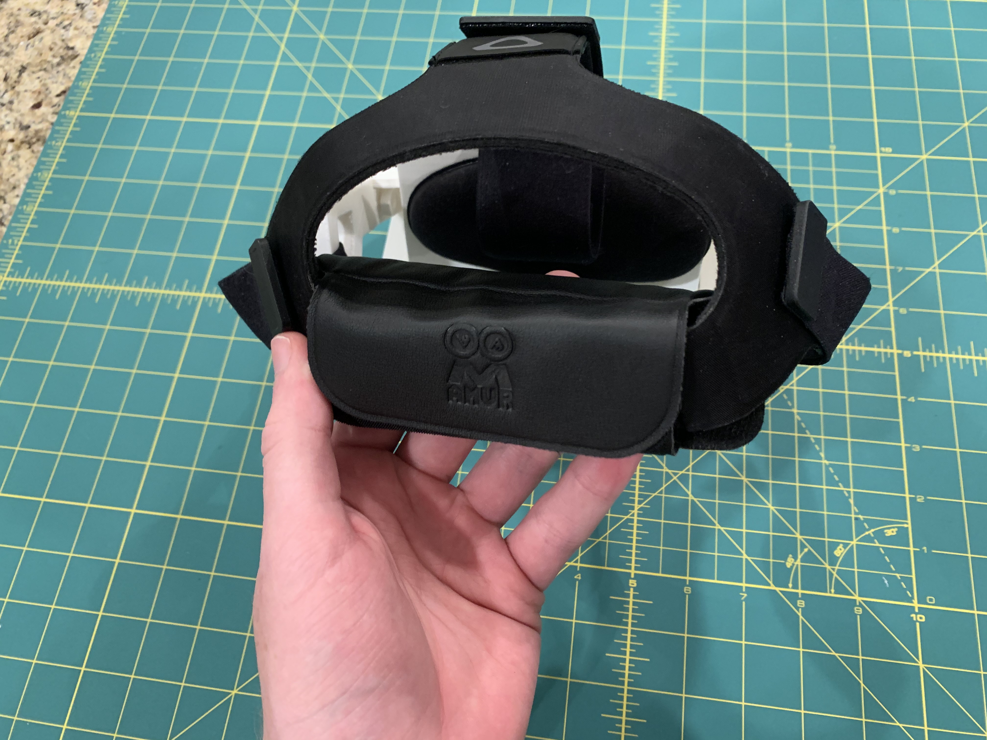
Now this section I would consider to be optional. But if you want to maximize comfort I would certainly purchase this padding from AMVR. It attaches to the back of the HTC Vive strap and cradles the head nicely. It has made using the Triton an order of magnitude more comfortable for prolonged sessions.